Blogs | Contact Us | News
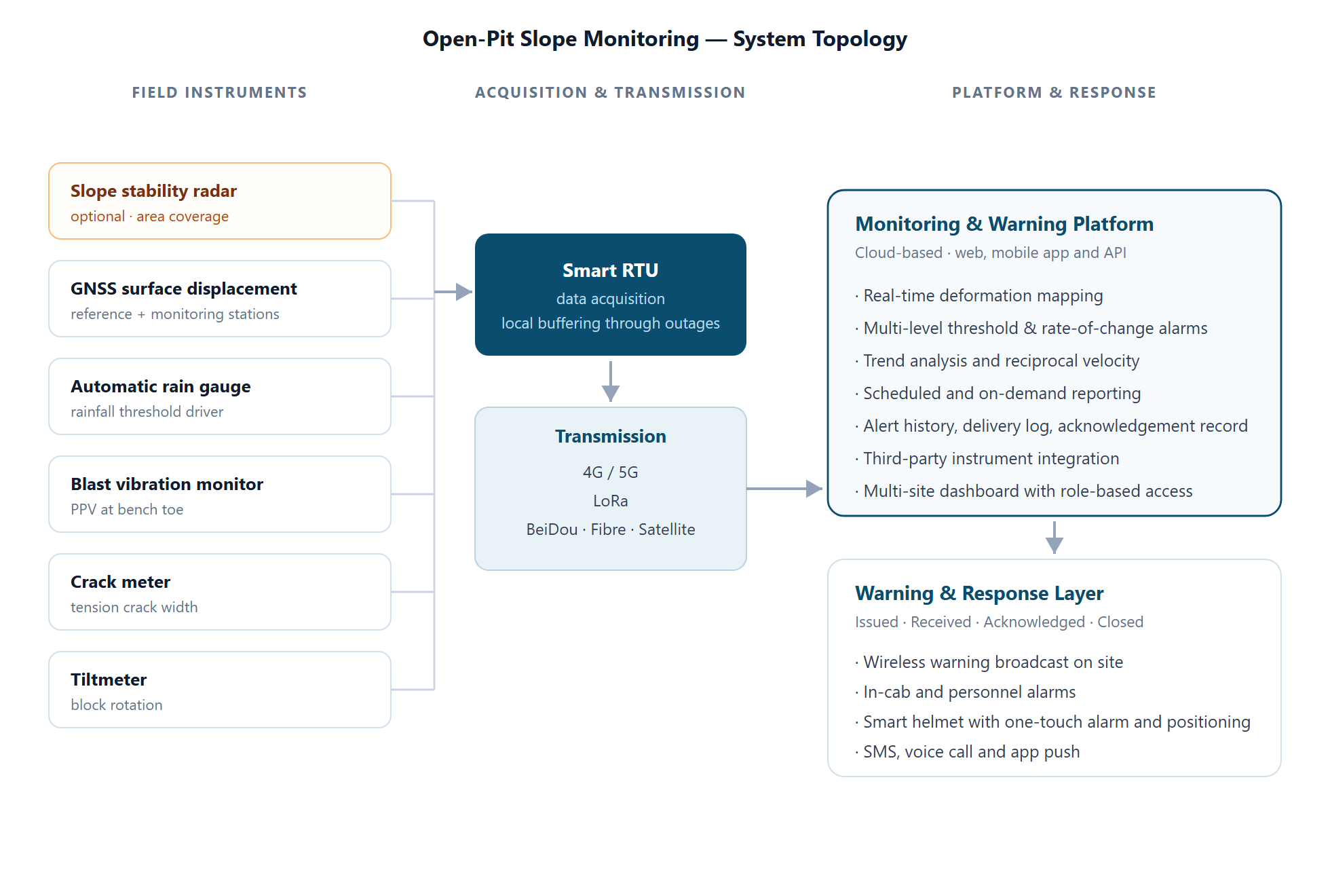
An integrated slope monitoring system for open-pit mines — slope stability radar for area coverage, GNSS and geotechnical instruments for point confirmation, and a monitoring platform that turns deformation data into alerts people actually acknowledge.
Built for mine operators, EPC contractors and geotechnical consultants who need continuous, defensible evidence of pit wall stability — not a monthly survey round.
Monitoring scope, alarm thresholds and reporting structure are normally justified against the following international guidance:
Each domain below addresses a distinct failure mechanism. The coverage and density figures are indicative engineering benchmarks — final scope follows site-specific design.
| Monitoring domain | Parameters | Instrument | Coverage / density (indicative) | Reference framework |
|---|---|---|---|---|
| Surface deformation Core | 3D displacement, velocity, acceleration, reciprocal velocity | Slope stability radar optional GNSS monitoring stations | Radar: full-wall continuous, no angular or range blind spots GNSS: 50–100 m spacing, ≥ 3 points per monitoring line | Guidelines for Open Pit Slope Design ISO 18674-1 MSHA 30 CFR 56 / 57 |
| Internal deformation | Deep-seated displacement, slip surface location and depth | In-place inclinometer, deep displacement station | Boreholes drilled at identified anomalies and critical sections | ISO 18674-3 |
| Groundwater | Pore water pressure, phreatic surface, groundwater level | Piezometer, pore pressure gauge | Along critical sections and behind active benches | ISO 18674-4 |
| Blast vibration Core | Peak particle velocity (PPV), dominant frequency | Blast vibration monitor | ≥ 3 points at the bench toe along the main sliding direction; more where the final wall is not yet formed | MSHA 30 CFR 56 / 57 USBM vibration criteria / DIN 4150-3 |
| Rainfall & meteorology Core | Rainfall intensity and accumulation, temperature, wind | Automatic weather station, rain gauge | Stable, unobstructed area on site; collector clearance angle ≤ 30° to the ridge line | Guidelines for Open Pit Slope Design ICMM |
| Cracking & rotation | Tension crack width and rate of opening; tilt and angular change | Crack meter, tiltmeter, tilt-acceleration sensor | Crack length > 5 m or width > 1 cm: instrument. Cracks > 10 m: spacing ≈ 10 m. Tiltmeters at identified blocks and along the main sliding direction | ISO 18674 series |
| Visual condition | Bench condition, surface water, fallen material, unauthorised access | Video surveillance | Viewshed covering active benches, access routes, haul roads and the pit perimeter | MSHA 30 CFR 56 / 57 |
| Personnel exposure optional | Position of people and equipment relative to the alert zone | Smart safety helmet, personnel positioning tags | All personnel working within the designated danger zone | ICMM critical control management |
The system is supplied as a configured set of modules. One of them — slope stability radar — is only specified where the consequence category, wall height or production exposure justify the investment. Everything below is available as an individual instrument for retrofit or as part of a complete system.
Function
The only module that provides area coverage. It sweeps the full pit wall continuously and produces a deformation map across a very large number of points, with no prior knowledge of where failure will start.
Siting principle
Positioned on a high point opposite the target area with a clear, unobstructed line of sight. Site selection determines coverage quality more than any other factor.
Specified when
High walls, critical infrastructure below the wall, high production exposure, or where the pit geometry makes point monitoring impractical. For lower-risk walls, a GNSS-and-instrument system with the same platform delivers full point monitoring and closed-loop alerting.
Function
Continuous 3D surface displacement at fixed points across the wall. Provides the long-term, absolute reference that confirms radar findings and builds the monitoring line the design basis depends on.
Siting principle
Reference stations outside the mining and influence zone on stable ground; monitoring stations on the wall where stability is poorest or deformation strongest — weak geological zones, areas below infrastructure or haul roads, zones affected by blasting, and sections above old workings.
Density
Typically 50–100 m apart, with no fewer than 3 points per monitoring line. Points kept more than 50 m from power lines and transformers, and more than 200 m from strong radio sources.
Function
Rainfall intensity and accumulation feed the threshold logic. Rainfall is the trigger behind a large share of slope failures, and rainfall-plus-deformation combined alarms are considerably more reliable than either alone.
Siting principle
Installed in a stable, level and open area of the site. Not placed on steep slopes, in gullies, in wind-exposed positions, or where the collector is shielded from the ridge line.
Standard
Automatic tipping-bucket rain gauge with a heated option for sites subject to snow or frost.
Function
Records peak particle velocity and frequency from every production blast. Blasting is a primary trigger of slope instability, and vibration data is what lets a mine adjust charge weight and timing before damage accumulates in the wall.
Siting principle
Points placed progressively outward from the blast centre. On a completed final wall, points go at the toe along the main sliding direction — no fewer than 3. Where the final wall is not yet formed, points go at the temporary bench toe, again no fewer than 3.
Alarm basis
Set against an allowable vibration velocity at the bench toe, determined by site-specific blast vibration assessment. Common international reference criteria are the USBM vibration guidelines and DIN 4150-3.
Function
Tension cracks are the visible precursor to planar, wedge and toppling failure. Measuring crack width and the rate of opening converts an observation into a trend line that supports a warning.
Siting principle
Instruments installed where crack length exceeds 5 m with width greater than 1 cm and depth greater than 2 m. Cracks longer than 10 m are instrumented at approximately 10 m spacing. On abandoned working faces, a crack meter is also required where engineering activity or critical infrastructure lies downslope.
Orientation
Host unit mounted on the downslope side of the crack, anchor on the upslope side. Sensor base line parallel or orthogonal to the movement axis, with the mounting surface accurate to within 3°.
Function
Detects early rotation of discrete blocks before measurable displacement develops — usually the earliest indication that a block has been released.
Siting principle
Installed on deformed blocks or at pronounced deformation, on rock slopes and along retaining structures. Points follow the main sliding direction or the strike of the collapse zone, with additional points where the span exceeds 30 m. Avoid low ground subject to ponding, buried services, positions with significant vibration, and locations without a clear view of the sky.
Mounting
Small level observation pier cast on site. The sensor mounting face must sit flush against the measured surface and be as level as possible. Can be installed horizontally or vertically.
Function
Carries the alert from the platform to a person who confirms it. Covers wireless warning broadcast on site, in-cab and personnel alarms, SMS, voice call and app notification — with acknowledgement tracking and automatic escalation.
Siting principle
Broadcast units placed outside control rooms, in high-threat zones and in areas where personnel concentrate, mounted as high as practical for coverage.
Closed loop
Issued · Received · Acknowledged · Closed. An alert that is not acknowledged within the configured window escalates automatically to the next level of responsibility.
Also available
In-place inclinometer for internal deformation (ISO 18674-3); piezometer and pore pressure gauge for groundwater (ISO 18674-4); video surveillance; personnel positioning; UAV survey; strain gauges.
Why they matter
Internal deformation and pore pressure answer why and how deep a slope is moving, which surface instruments alone cannot. Where a deep-seated failure surface is credible, these are not optional in engineering terms — they are the instruments that distinguish surface creep from a deep-seated mechanism and change the response entirely.

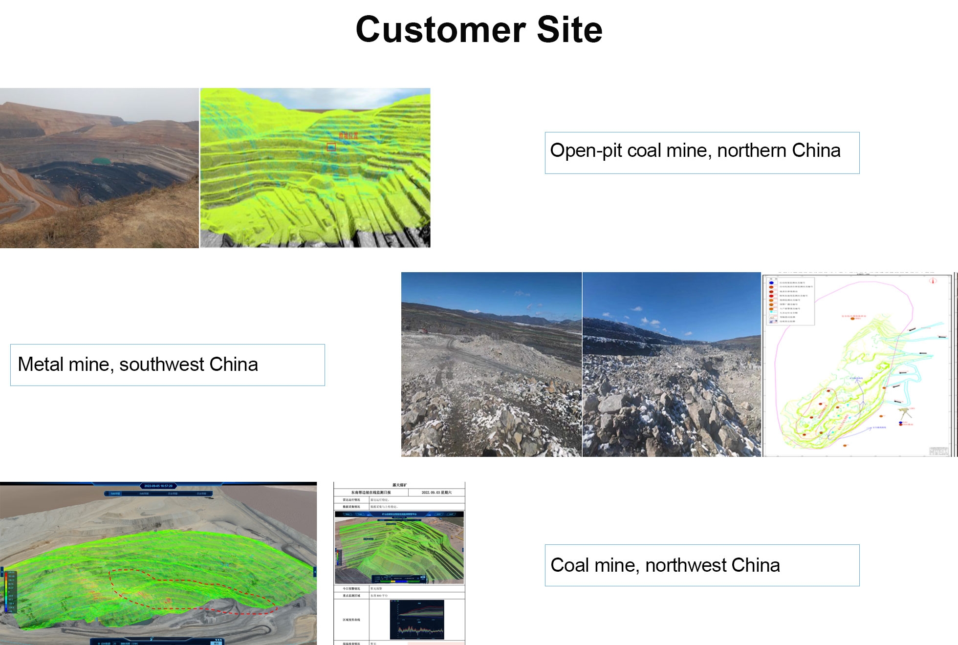
Reference installations demonstrating three different capabilities: early warning of an actual failure, instrument scope matched to a classified risk level, and detection of a hidden structural feature.
In May 2020 the system issued a successful early warning of a small slope failure. The mine secured the area in advance, avoiding injury and equipment loss.
The pit wall is approximately 300 m long and around 20 m high in places, worked at 30–42° with locally steeper faces in a benched configuration.
Continuous slope monitoring began in March 2021 on the north-east wall of the pit.

Radar is not mandatory. It is the only module that provides area coverage of the whole wall, so it is specified where wall height, consequence category or production exposure justify the investment. A system built on GNSS, crack meters, tiltmeters, rain gauge and blast vibration monitoring — with the same platform and the same closed-loop alerting — is a complete point-based monitoring system, and the radar can be added later without replacing anything. Systems are normally proposed in three tiers so you can see exactly what changes between them.
The platform supports a range of standard industrial interfaces for third-party instruments. Compatibility is confirmed during system design, before any commitment is made. Where an existing instrument cannot be integrated, we will say so at that stage.
Deformation accuracy is ≤ 0.1 mm at a maximum detection range of ≥ 5,000 m, with a range resolution of ≤ 0.2 m and an azimuth resolution of ≤ 7.5 mrad. Practical performance depends on site conditions, in particular line of sight and atmospheric variability across the measurement path, and is confirmed during the site review.
The radar draws ≤ 40 W and the field instruments are low-power by design, which makes solar supply practical at remote sites.
Multiple redundant paths are supported — 4G / 5G, LoRa, BeiDou short message, fibre and satellite — selected per site according to coverage and terrain. The RTU buffers locally at the measurement cluster, so a communication outage does not create a data gap.
Yes. The platform supports scheduled and on-demand exports with time-stamped records, alert history, delivery logs, acknowledgement timestamps and trend data — structured for engineering review and regulatory reporting rather than for internal dashboards only.
Scope follows the failure mechanisms credible at your site and the consequence category of the assets below the wall, not a standard package. Alarm thresholds are set from the baseline records established during commissioning, with rate-of-change and velocity alarms configured alongside absolute displacement limits. Final design is normally reviewed and signed off by your Engineer of Record.
Yes. We provide datasheets, test reports and a technical specification template that can be adapted to your tender format. We also work directly to specifications written by consultants.
Full certification documentation is available on request, and we will confirm the current certificate list for your market during technical discussion.
Yes. A significant part of our work is supplying EPC contractors, systems integrators and geotechnical consultants who specify the system for their client. We can supply to your specification or provide design support.
Send us your slope geometry, design parameters and current monitoring arrangements. We will respond with an indicative instrument layout, a radar siting recommendation and budget pricing.
We typically respond within one business day. Technical proposals are prepared by an engineer, not a sales template.
content is empty!
content is empty!